TM 5-2350-377-13&P
0035
INSTALLATION
1.
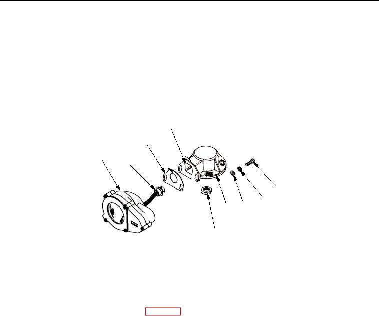
Apply sealant adhesive on new gasket (Figure 2, Item 3) with acid swabbing brush. Position gasket
(Figure 2, Item 3) on support (Figure 2, Item 8).
2.
Feed connector (Figure 2, Item 2) through hole (Figure 2, Item 4) in support (Figure 2, Item 8). Install jam nut
(Figure 2, Item 9) to connector (Figure 2, Item 2).
3.
Position body (Figure 2, Item 1) on support (Figure 2, Item 8). Install three screws (Figure 2, Item 5), new
lockwashers (Figure 2, Item 6), and washers (Figure 2, Item 7) to support (Figure 2, Item 8) and body
(Figure 2, Item 1).
4
3
1
2
5
6
7
8
9
M0018HBF
Figure 2. Headlight Support Installation.
END OF TASK
FOLLOW-ON MAINTENANCE
1.
Install left or right headlight assembly (WP 0030).
2.
Connect negative battery cable (TM 5-2350-262-20).
3.
Unblock front of vehicle (TM 5-2350-262-20).
END OF TASK
END OF WORK PACKAGE
0035-3/4 blank
03/15/2011Rel(1.8)root(maintwp)wpno(M00008)

