TM 5-3800-205-23-2
ELEVATOR ASSEMBLY ADJUSTMENT
THIS WORK PACKAGE COVERS
Adjustment
INITIAL SETUP
Equipment Condition - Continued
Maintenance Level
Unit
Scraper bowl lowered to ground (TM 5-3800-205-
10-1)
Tools and Special Tools
Parking brake applied (TM 5-3800-205-10-1)
Tool kit, general mechanic's (Item 33, WP 0048 00)
Wheels chocked (TM 5-3800-205-10-1)
Equipment Condition
Battery disconnect switch in OFF position (TM 5-
Machine parked on hard, level surface (TM 5-3800-
3800-205-10-1)
205-10-1)
ADJUSTMENT
NOTE
Clearance between elevator flights and top of cutting edge may be adjusted. Distance between
top of cutting edge and elevator flight is set at factory at approximately 2.4 in. (61 mm). Two
shims are located at top of bracket when machine is shipped from factory. Brackets are located
on each side of the bowl. Shims must be equally placed on each of the brackets.
Shims may need to be added to top of bracket when working on material which is compacted.
Space that is between cutting edge and elevator flight will become wider. Shims may also need
to be added to top of bracket when components of elevator become worn.
Shims may need to be moved from top of bracket when working on loose material. Space
between cutting edge and elevator flight will become narrower.
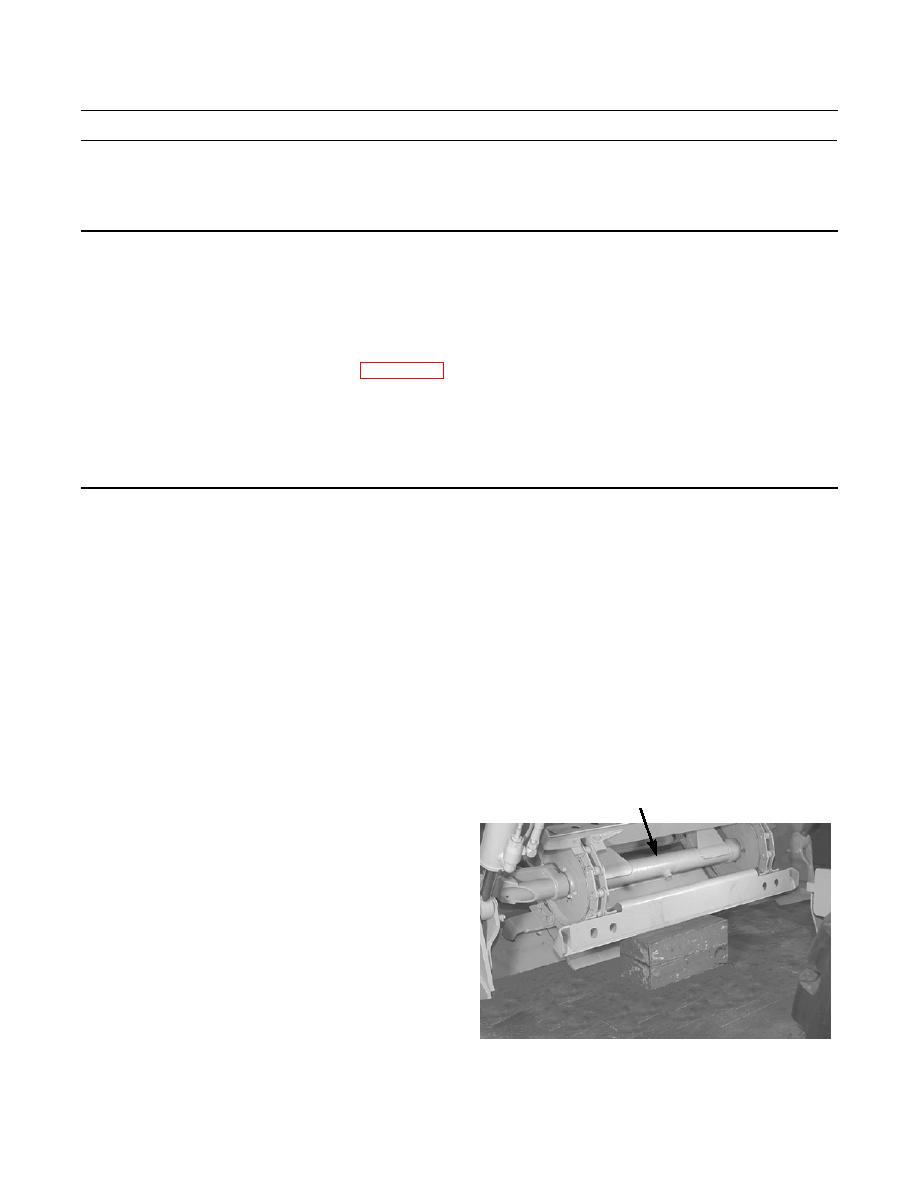
1.
Raise front of elevator (1) with jack or hoist and place
1
blocks or stands under front of elevator. Lower eleva-
tor until resting on blocks or stands.
390-1150


