TM 5-3805-248-23-2
GOVERNOR ASSEMBLY REPAIR - CONTINUED
0354 00
FUEL SETTING PROCEDURE - CONTINUED
13.
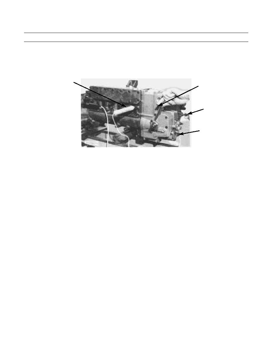
Secure clip end of circuit tester (99) to insulated terminal (100) and attach other end to good electrical ground.
14.
Hold governor control lever in FULL LOAD position (rotate governor shaft clockwise).
GOVERNOR
99
CONTROL LEVER
97
100
394-1714
CAUTION
DO NOT turn the rod any further in if the rod begins to tighten. Damage to the governor can occur if the rod
is turned in further.
NOTE
When the rod is turned out, there can be a small initial movement of the dial indicator hands. Hands will
stop moving while the rod is turned out for approximately 1-1/2 additional turns. Indicator hands will
begin to move again and will follow the turning of rod until setting is reached. It is important that the
rod be turned slowly so rack can follow the governor components.
If rod is turned out too fast, a wrong measurement can be read on the dial indicator as the light comes
on. Repeat steps 15 and 17 to make sure the correct measurement is taken.
15.
Turn rod (97) of compressor assembly in (clockwise) until dial indicator hands move an additional -0.0787 in. (-2 mm)
after light goes out (two complete revolutions of large needle on dial indicator).
0354 00-15


